Skip to content

wrc-537

2 posts with the tag “wrc-537”

Are You Still Doing Pressure Vessel Calcs by Hand? Here’s What It’s Costing You.

If you are still building pressure-vessel calculations by hand or stitching them together in Excel, you are paying a tax you cannot see—on schedule, quality and reputation. Every hour spent transcribing tables, eyeballing graphs, copying values between sheets or unpicking someone else’s formulas is an hour not spent on design intent, failure modes or scope. Reviewers feel this pain as much as engineers. RPEQs are routinely handed sprawling workbooks with hidden cells, legacy assumptions and no reliable way to trace which version produced the PDF on their desk. The problem is not that spreadsheets are always wrong; it is that you cannot quickly prove they are right. And this cost does not stop at nozzles; it affects the routine calculations that make up every real project.

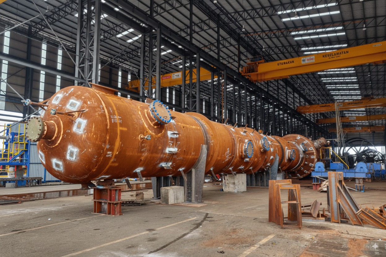
Modern pressure vessel facility at dusk.

Context: production plants carry high downtime costs—clarity and traceability reduce risk.


The Hidden Costs You’re Already Paying

Hidden costs of manual calculations: time loss, rework, review friction.

Context: small frictions—transcription, rework and audit gaps—accumulate into delays and uncertainty.


Manual workflows rarely fail loudly; they leak time and certainty. The first leak is transcription. Engineers move between Code clauses, curve fits and internal check tables, re-typing or copy-pasting values. Even when every number is correct, the task consumes attention better spent on the real engineering problem solving that delivers value. The second leak is rework. A late change to a nozzle load case or vessel thickness forces you to thread new numbers through a workbook built earlier for a different geometry. You spend valuable time reacquainting yourself with your own logic before you can safely adjust it. The third leak is review friction. A conscientious reviewer wants evidence that inputs, method and outputs are consistent and traceable. If the workbook does not surface assumptions, Code edition and calculation method on page one, the reviewer slows down and rebuilds trust from first principles. Multiplied across every calculation package in a job, the compounding effect becomes obvious.

Why Spreadsheets Fail in Engineering Contexts

Spreadsheets are powerful and familiar, but they are an undisciplined medium for safety-critical design work. In pressure-vessel practice, the same failure modes recur. Version drift is the most corrosive. Files are emailed, saved to network drives and cloned for similar jobs. Months later, few can say with confidence which workbook created the signed report, or whether it contains the late-stage change the client requested. Hard-coded cells are the quiet killer. A formula replaced with a value during troubleshooting becomes permanent. The spreadsheet still calculates, but the dependency chain is broken and future edits no longer propagate as intended. Unit errors creep in when a single kN entered as N slips through unchallenged. Here is how that plays out in numbers. A piping moment of 12 kN·m on a nozzle gets typed as 12 into a cell the formula reads in N·m — the moment is now a thousand times too small. Local stress from an external moment scales linearly with that moment, so the 120 MPa it should contribute collapses to 0.12 MPa. The sheet adds it to, say, 60 MPa of pressure stress and reports about 60 MPa against a 150 MPa limit: a comfortable pass, and a perfectly plausible number on screen. The true combined stress is 180 MPa and the nozzle fails the check. The reverse slip — N·m typed into a kN·m cell — inflates the result a thousandfold and gets caught by eyeball; it is the low-by-a-thousand direction that reads clean, prints clean and gets signed. Copy-and-paste mistakes are obvious when they are found and expensive when they are not. A range offset by one row will feed the right-looking number into the wrong place and no one is warned. The same patterns show up whether you are doing a quick WRC check, a head thickness, a nozzle reinforcement or a flange assessment.

Opacity compounds the problem. Spreadsheets make it easy to bury logic behind named ranges and helper tabs. That can be convenient for the author and frustrating for the reviewer who is accountable for the final sign-off. When a calculation cannot be audited quickly, the conservative response is to repeat it independently. Your submission is then treated as an attachment to, rather than the basis for, approval.

Why Code Tables and Graphs Are Hard to Automate by Hand

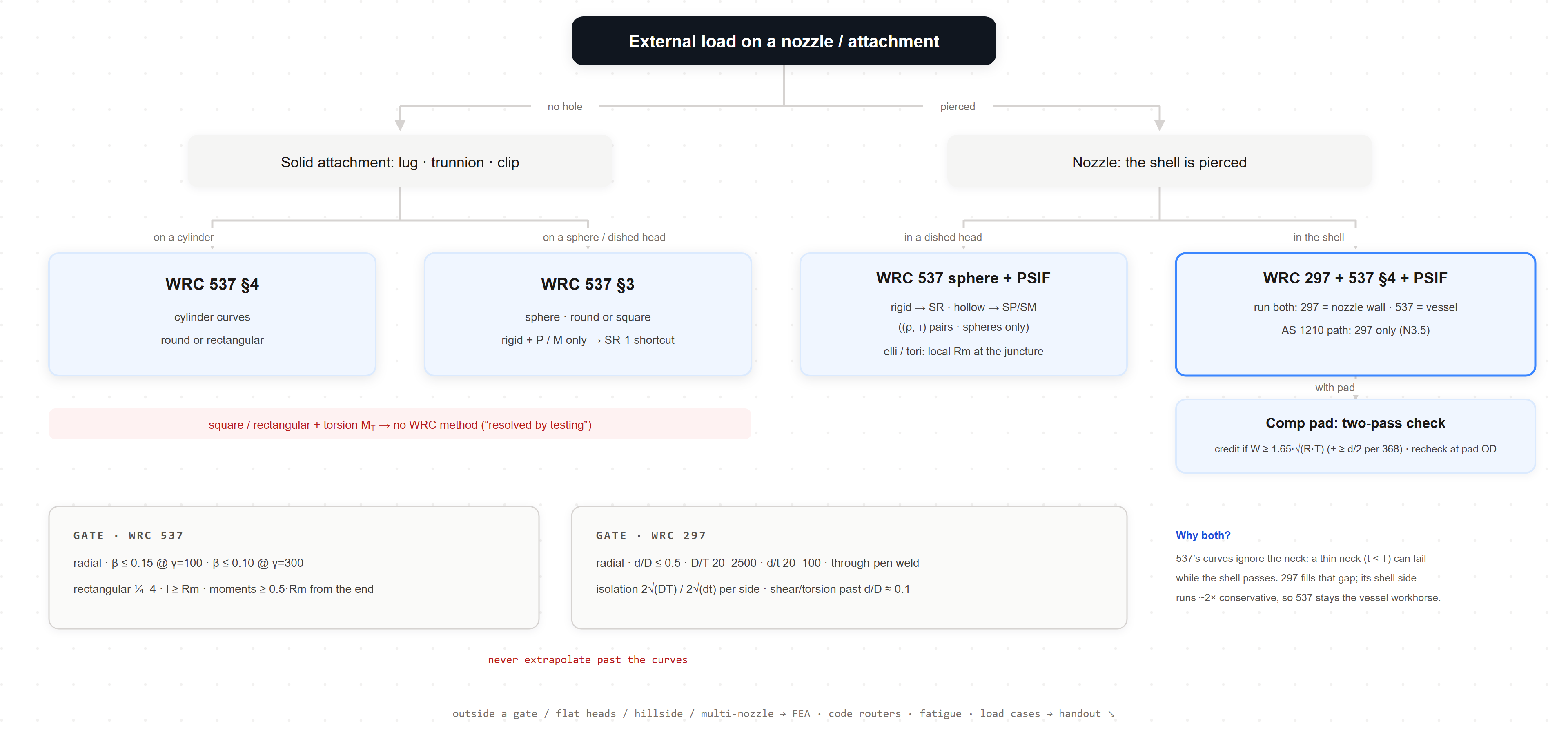
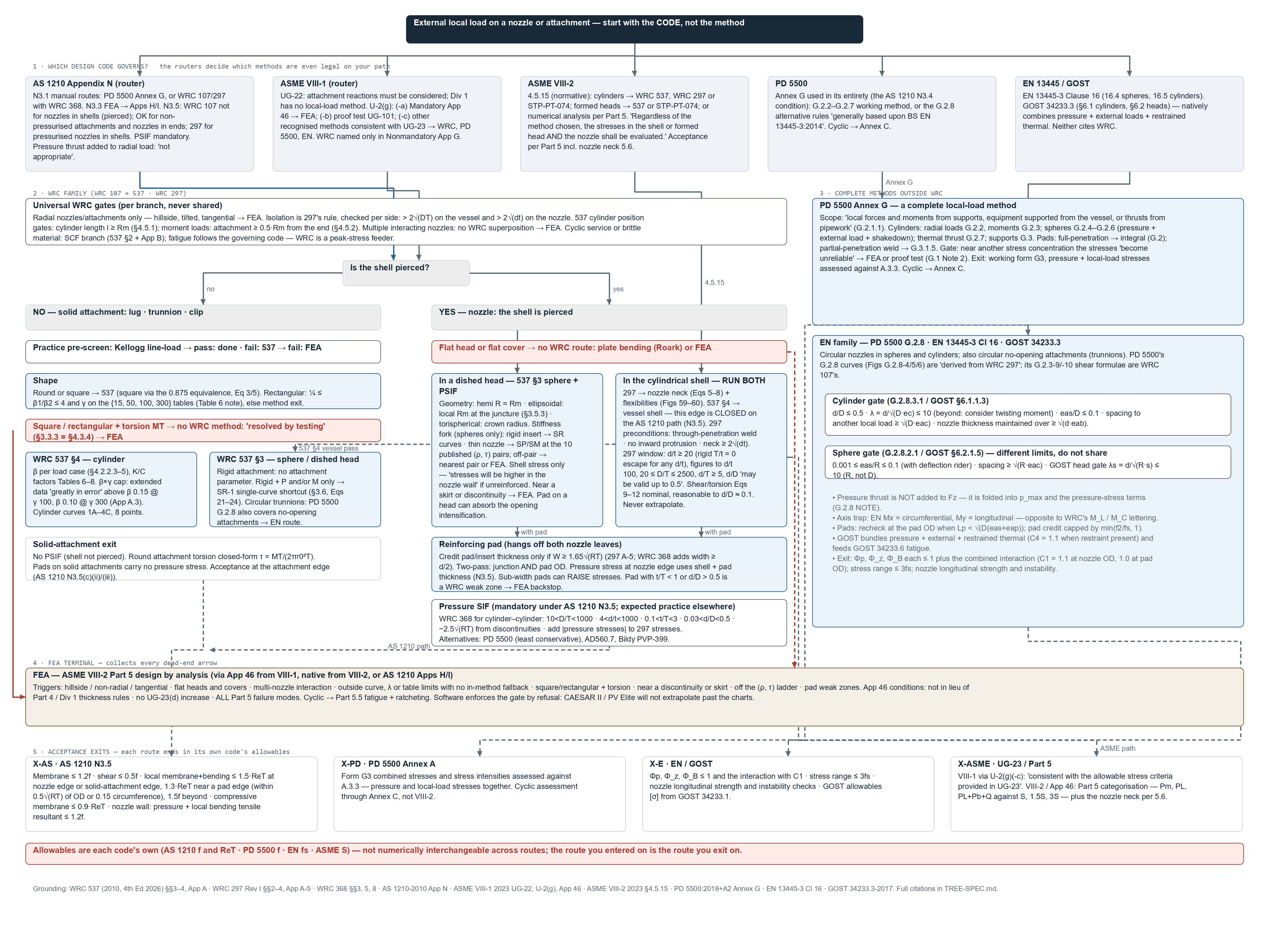
Pressure-vessel calculations depend on accepted methods. For nozzle-to-shell checks, WRC 537 and WRC 297 are used every day. The difficulty is not the mathematics; it is the mechanical work of interpreting limits, reading curves and applying the correct set of coefficients for the geometry at hand. When engineers translate those steps into spreadsheets, they recreate the method in fragments: a table entered here, an interpolation there, a chart image pasted as a reminder. Every recreation is a chance to mis-key a coefficient, reference the wrong region or step outside the method’s geometry limits without knowing. Excel can interpolate numbers; it cannot warn you that your d/D or T/t places the case outside the bulletin’s envelope unless you have built, tested and maintained that guardrail for every case.

When Excel Is Still Fine

There is nothing inherently unprofessional about Excel. For one-off scoping exercises, hand checks, early feasibility and simple tests, a small, well-annotated sheet can be more efficient than a full calculator. If you are exploring whether a concept is viable, the overhead of formal documentation can be counterproductive. Excel is also reasonable for stable, mature internal tools when they are tightly controlled, guarded by validation and used by a small, trained group.

The test is simple. If the calculation matters enough to be reviewed outside the author’s immediate team, and if it will be repeated, varied or reused, a spreadsheet starts to work against you. The more stakeholders involved, the more your tool needs to be standardised, self-validating and auditable. That is as true for a nozzle load case as it is for head sizing, reinforcement area or a flange capacity check.

What a Modern, Standardised Workflow Looks Like

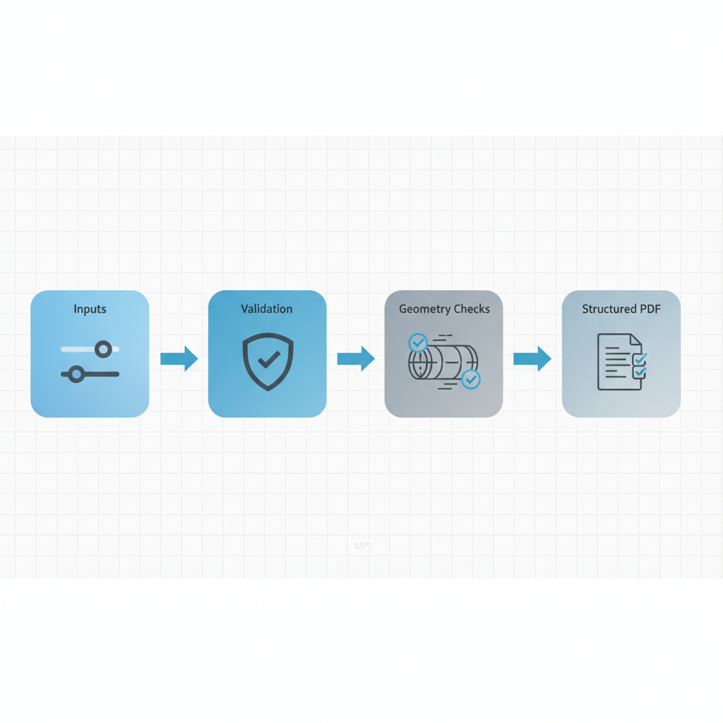
Modern PV Cloud workflow: Inputs → Validation → Geometry Checks → Structured PDF.

Context: structured inputs, automatic validation, geometry checks and a traceable PDF reduce rework and speed review.


A modern workflow does not eliminate engineering judgement; it protects it. The starting point is a purpose-built calculator that implements accepted methods and embeds the tables and curve-fit equations rather than asking the user to transcribe them. It checks geometry limits up front and reports when the method does not apply. It treats units explicitly, validates inputs as they are entered and makes assumptions visible. It records the calculation version, the Code edition and the user who ran it.

The outputs are structured and repeatable. Inputs, method and results are captured in a report that reads the way a reviewer thinks. The PDF references the calculator version and change log. If a change is made, regenerating the report creates a new entry that records what changed and when. Sharing is deliberate. A reviewer receives an authoritative record, not a forked spreadsheet they will inevitably edit. If a new load case is required, it can be created without breaking the original record.

Moving from Excel to PV Cloud Without Disruption

If you want to see the difference on real work, start with the WRC 537 / WRC 297 nozzle calculator in PV Cloud (WRC 537 supersedes the legacy WRC 107), run your next case and compare the experience and the output to your current spreadsheet. You will spend less time wrestling with the workbook and more time doing engineering—and you will produce a report a reviewer can trust months from now when the job is revisited.

Use the nozzle calculator free at pv-cloud.com.


Closing

Pressure-vessel engineering will always require judgement. That judgement deserves a workflow that does not dilute it with transcription, version drift and audit gaps. PV Cloud makes the accepted methods easier to apply, the limits harder to miss and the results simpler to review. The outcome is not a shortcut around RPEQ sign-off; it is a higher-quality submission to it—delivered faster, with fewer surprises, and with a traceable record you can defend.

WRC 537 vs WRC 297: Finally Making Sense of Nozzle Stress Calculations

Pressure vessel

Why these bulletins matter

Specifications still lean on Welding Research Council bulletins whenever nozzle loads come up, and the references are often a generation out of date. The job of these methods is to estimate local stresses at a nozzle or attachment from external piping loads, in a way a reviewer can follow and a code margin can be applied to. Pick the wrong bulletin, or claim more from it than it actually delivers, and the review drags: questions multiply, someone reruns the numbers, and the schedule wears it. Pick the right one and state its limits up front, and the conversation gets short. This post sets out what WRC 537 and WRC 297 each actually cover — from the bulletins themselves, not from folklore.

WRC 107 became WRC 537 — same method, better data

WRC 107 was published in 1965 and revised several times through 1979. It packaged Professor P. P. Bijlaard’s shell solutions into non-dimensional design curves: read the curve, take a membrane force and a bending moment, combine them into surface stresses at the attachment-to-shell junction. Generations of engineers learned nozzle loads from it, and plenty of specifications still cite it.

In 2010 WRC 537 superseded it. WRC 537 is not a new theory. It is the WRC 107 method reissued with corrected data and precision curve-fit equations — every figure now carries polynomial coefficients, so software (and careful spreadsheet users) evaluate the fit instead of eyeballing a log-scale chart. The known errata from the 107 revision history, such as the reversed curve labels documented in its Appendix A, are folded in. If your specification says WRC 107, treat that as legacy wording and run WRC 537. The answer is the same method with the housekeeping done.

What WRC 537 actually gives you

WRC 537’s own statement of its limits is blunt, and it applies to the whole bulletin: the procedure yields “stresses in the shell, but not in the nozzle” (§3.5.1, repeated for cylinders in §4.5.3). It computes surface stresses in the vessel wall at eight points around the attachment junction — four positions, inner and outer surface. What it assumes about the attachment differs between its two halves, and the difference is worth knowing.

Cylindrical shells (Section 4). The curves treat the attachment as a loaded footprint on an unpenetrated shell — there is no hole and no nozzle wall in the model. WRC 297’s Appendix C says exactly that when comparing the two bulletins. Round attachments enter through an equivalent square: the attachment parameter is taken as 0.875·r₀/Rm (§4.2.2.1). Square and rectangular solid footprints are handled directly, rectangles via multiplication factors on the square case. There is no hollow-attachment case for cylinders: nozzle wall thickness never appears in the Section 4 parameters, so a thin flexible nozzle and a solid trunnion of the same outside radius produce identical shell stresses.

Spherical shells (Section 3). Here the bulletin does distinguish a rigid solid insert (§3.2.2.1) from a hollow nozzle (§3.2.2.2), and the nozzle wall enters the solution through the parameters rm/t and T/t. There is even a hollow square case for box-section attachments (§3.2.2.3). So the sphere curves account for nozzle-wall flexibility when computing the shell stresses — but the output is still shell stresses. Section 3.5.1 says so in terms, and Appendix A quotes the underlying assessment: solutions that give only shell stresses “may seriously underestimate the peak stress” when loads come in through a thin-walled nozzle. Both halves of the bulletin carry the same warning — the nozzle wall is most likely to govern when the opening is unreinforced, or when the reinforcement sits on the vessel rather than the nozzle.

Ellipsoidal heads. WRC 537 §3.5.3 allows the spherical method on ellipsoidal heads with “reasonable accuracy” if you use the local mean radius of the head at the attachment. For a nozzle in the crown of a 2:1 semi-ellipsoidal head that local spherical radius is about 0.9D — not the nominal head radius and not a mean of anything. The idealisation is at its best in the crown, where curvature is nearly constant; toward the knuckle the meridional radius changes rapidly and treating the spot as a sphere becomes progressively harder to defend.

What WRC 297 adds

WRC 297 (1984, revised 1987) is written as a supplement to WRC 107, and it is deliberately narrow: cylindrical nozzles radially attached to cylindrical vessels, nothing else. Within that geometry it does two things the older bulletin does not.

First, it models the junction rather than a footprint. The method is C. R. Steele’s thin-shell solution of two intersecting cylinders: the opening is real and the nozzle is a flexible shell, not a rigid plug. That is what lets 297 reach configurations 107/537 never covered — thinner nozzles, larger d/D, vessel D/T well beyond the Bijlaard curves.

Second, it reports stresses on both sides of the junction. The foreword states it plainly: stresses in both the nozzle and the vessel can be determined. Section 3 gives vessel surface stresses and nozzle axial stresses at the junction; nozzle circumferential membrane stress is set equal to the shell’s, and nozzle circumferential bending is neglected as insignificant.

The stated applicability limits (§3.2) are worth pinning to the wall: d/t ≥ 20, D/T ≥ 20 and d/T ≥ 5 for the thin-shell theory to hold, D/T ≤ 2500 as a recommended ceiling, curves plotted to d/t ≤ 100, and d/D up to about 0.5 depending on D/T. A thick nozzle acts as a nearly rigid insert, so vessel stresses stay reasonable at low d/t even though the nozzle-stress side of the method loses validity. The nozzle must be isolated (roughly 2√(DT) from any other discontinuity), must not protrude inside the vessel, and must be attached by a through-penetration weld.

Scope at a glance

This table is the part to keep. It replaces the folklore versions — “537 is shells, 297 is nozzles” — with what the bulletins actually say.

MethodGeometry coveredAttachment as modelledWhat stress you get, and where
WRC 537, Section 4Cylindrical shell, radial attachmentSolid footprint on an unpenetrated shell; round attachments via the 0.875·r₀ equivalent square; square and rectangular solid shapes directly; no hollow case, nozzle wall ignoredShell stresses only, at 8 points around the junction (§4.5.3)
WRC 537, Section 3Spherical shell; ellipsoidal head treated as a local sphere using the crown radius at the attachment (§3.5.3)Rigid solid insert, or hollow round nozzle (rm/t, T/t), or hollow square section — nozzle-wall flexibility enters the shell solutionShell stresses only, at 8 points (§3.5.1); explicit warning that the nozzle wall may govern
WRC 297Radial cylindrical nozzle on a cylindrical vessel, that geometry onlyFlexible thin-shell nozzle intersecting the vessel (Steele); opening modelled; d/t ≥ 20, 20 ≤ D/T ≤ 2500, d/T ≥ 5, d/D ≲ 0.5Shell and nozzle stresses at the junction — vessel surface stresses plus nozzle axial and circumferential membrane

So which one do you run?

For the classic radial cylinder-on-cylinder nozzle, common practice is to run both: 537 for the vessel-side check reviewers grew up with, 297 for the nozzle wall and for geometry 537’s cylinder curves cannot reach. The publisher takes the same view — WRC sells 107/297 “as an integral set.” But be clear about what that pairing is: a practice preference, not a scope boundary. WRC 297 is not merely a nozzle-stress annex; it produces its own vessel stresses, from a model that includes the opening, where 537’s cylinder curves assume an unpenetrated shell. The two therefore give different shell stresses for the same loads — 297’s Appendix C compares them and finds consistent trends but real differences either side, depending on nozzle-neck thickness. Which set to trust, and when the difference matters, is an argument reviewers genuinely have; it deserves its own post and will get one.

For spheres, dished heads, trunnions, and rectangular attachments, 537 is the only one of the pair that applies. Take its shell stresses, use the local crown radius on ellipsoidal heads, and deal with the nozzle wall separately — the bulletin itself tells you it has not checked it for you.

When the bulletins are not enough

The envelope is the whole deal. Inside it — single, isolated, radial attachment; geometry within the stated ratios — the bulletin methods are fast, repeatable and defensible, and there is no engineering reason to reach past them. Outside it — hillside and lateral nozzles, closely spaced openings interacting, reinforcing pads (which neither bulletin’s curves model), parameters off the end of the charts — forcing a bulletin to fit produces numbers nobody should defend. That is the point to escalate to a proper local analysis, and to say so in the calc rather than bury it.

Key takeaways

WRC 537 has replaced WRC 107; cite and run 537. It delivers shell stresses only — its own limitation sections say so for both cylinders and spheres — and its cylinder curves never see the nozzle wall at all, while its sphere curves at least feel the nozzle’s flexibility. WRC 297 covers one geometry, the radial cylinder-on-cylinder junction, and there it gives both shell and nozzle stresses from a flexible-nozzle model with hard applicability limits. Running 537 and 297 together on that geometry is sound practice, provided you understand you are looking at two different models of the same junction, not two halves of one answer.

A worked example is coming: a full WRC 537 cylinder calculation, all eight stress locations by hand, checked against a finite-element run of the same junction.

Run WRC 537 and 297 with PV Cloud

PV Cloud runs WRC 537 and WRC 297 side by side, with the geometry limits checked up front and the curve-fit equations evaluated exactly — no chart squinting, no spreadsheet archaeology.

Calculate with PV Cloud →