
Which Nozzle Method, When: The Full WRC Decision Tree

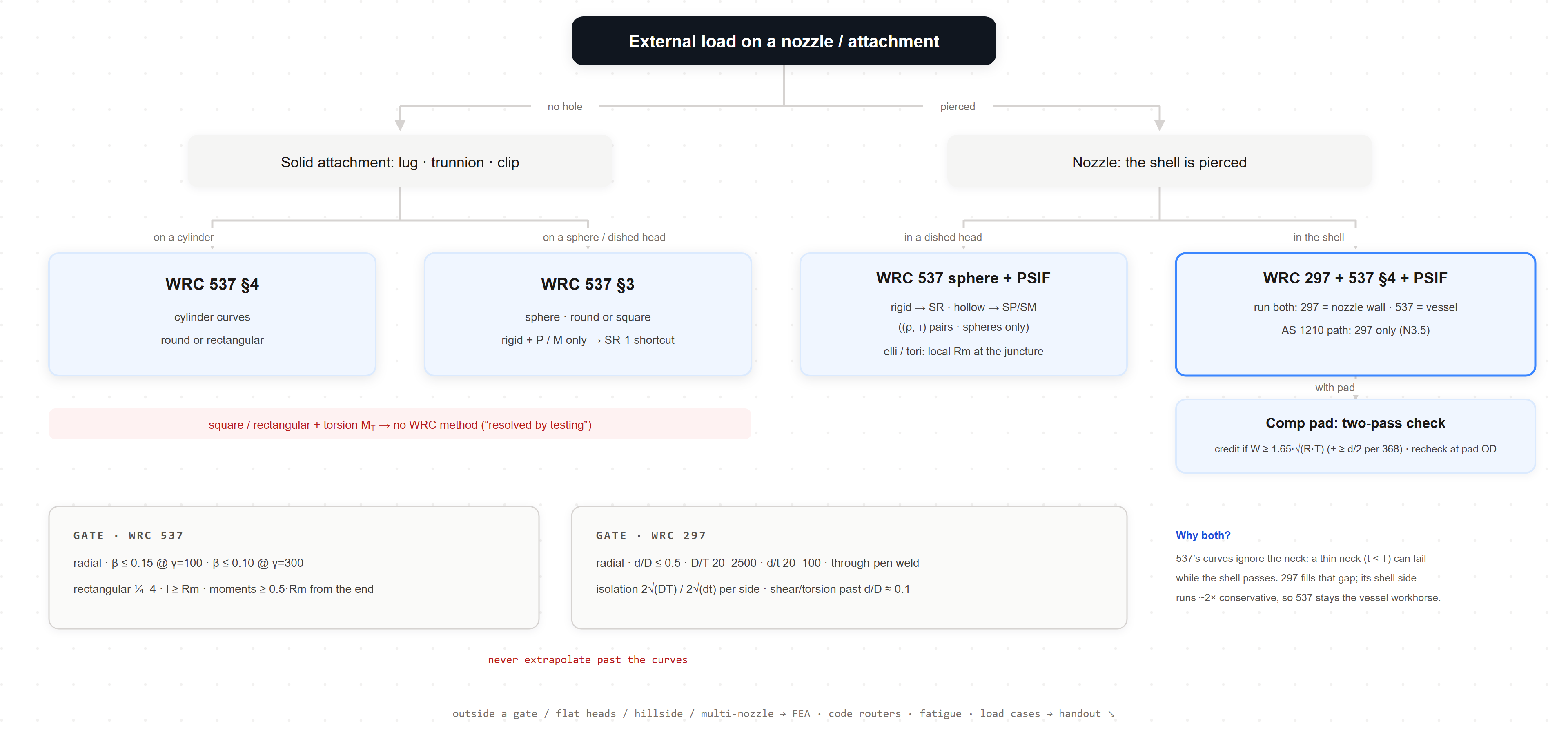
This is the written version of the decision tree from my Pressure Equipment Workshop 2026 talk. The slide above is the WRC-only core; this post is the full tree, including the layer the slide deliberately skips: the design codes that decide which methods you’re even allowed to use.
The full tree
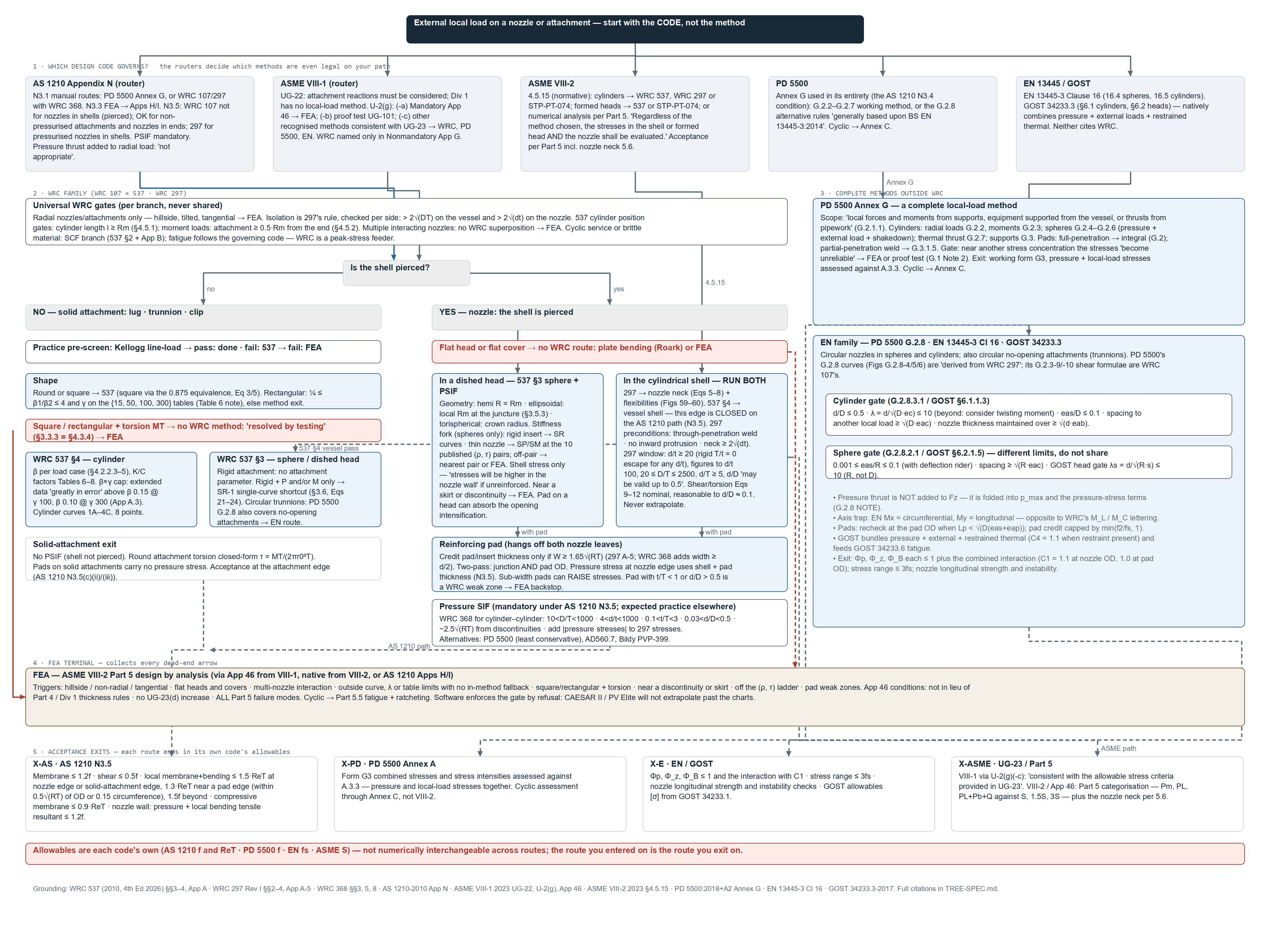
Download it as SVG (scales to any print size) or PNG. The rest of this post walks it top to bottom.
Every claim here traces to the owning document. Where something is practice rather than code, I say so.
Layer zero: the code decides first
Before you pick a method, your design code has opinions:
- ASME VIII Division 2 is the surprise: paragraph 4.5.15 is normative. For nozzles in cylindrical shells, local stresses “shall be in accordance with WRC 537 (supersedes WRC 107), WRC 297, or ASME STP-PT-074”; for formed heads, WRC 537 or STP-PT-074; numerical analysis is the sanctioned alternative. The code doesn’t just tolerate the bulletins, it names them.
- ASME VIII Division 1 names no method in its mandatory rules. UG-22 makes you consider the loads, U-2(g) hands the detail to the designer with three routes (Mandatory Appendix 46 into Div 2 Part 5, proof test, or “other recognized and generally accepted methods”), and Nonmandatory Appendix G suggests WRC 107/297 for supports and attachments.
- AS 1210 Appendix N names WRC 107, 297, and 368, with a restriction most people have never read: WRC 107 “should not be used for nozzles in shells”, it stays for non-pressurised attachments and nozzles in ends; WRC 297 is the one for pressurised nozzles in shells. App N also mandates the pressure SIF (more below) and accepts PD 5500 “Appendix G” as a complete alternative, “provided it is used in its entirety”.
- PD 5500 Annex G is a full local-load method of its own, and it openly shares blood with the bulletins: two of its cylinder equations “are from WRC 107” and its nozzle stress concentration factors are “derived from Welding Research Council Bulletin No. 297”, by its own footnotes.
- EN 13445-3 Clause 16 is the same family as PD 5500’s G.2.8 (which is “generally based upon BS EN 13445-3”).
- GOST 34233.3 never cites WRC at all. It built its own equivalent, and in one respect a stronger one: pressure, external nozzle loads, and restrained thermal expansion combine in a single check.
The WRC trunk
First question: is the shell pierced?
No hole: solid attachments (lugs, trunnions, clips)
WRC 537 §4 for cylinders (round or rectangular attachments), §3 for spheres and dished heads (round or square). A rigid attachment carrying only radial load and/or moment gets the SR-1 single-curve shortcut. No hole means no pressure SIF (AS 1210 N3.5).
Two hard stops on this branch:
- Square or rectangular attachment plus torsion: no WRC method exists. Both §3.3.3 and §4.3.4 say, in identical words, that acceptable methods “are not available at this time” and the problem should be “resolved by testing”. Round attachments get a closed-form torsion shear.
- A lug on a flat cover: no curvature, no WRC route. Plate bending or FEA.
Nozzle in a dished head
WRC 537’s sphere method plus a pressure SIF. Inside it hides a fork worth knowing: a rigid insert uses the SR curves with no attachment parameter, while a thin hollow nozzle uses the SP/SM curves, which exist for spheres only and only at ten published (ρ, τ) pairs, so software snaps to the nearest pair. Ellipsoidal and torispherical heads enter through the local radius at the juncture (crown radius for torispherical). And 537 itself warns the shell answer isn’t the whole story: “stresses will be higher in the nozzle wall… if the nozzle opening is not reinforced”.
Nozzle in the cylindrical shell: run both bulletins
The question the simple flowcharts skip: which stresses do you need?
- Nozzle neck stress — WRC 297 only. It models the actual opening and reads the nozzle wall; 537 alone can “seriously underestimate the peak stress” at a thin neck.
- Vessel shell stress — 537 §4 remains the workhorse. 297 reads the shell too, but its shell-side numbers commonly run around twice as conservative as FEA.
So practice, and the PV Cloud implementation, run both: 297 for the neck and flexibilities, 537 §4 for the vessel, plus the pressure SIF. One code-path exception: on the AS 1210 route, N3.5 closes the 537 edge for pierced shells, 297 carries the check alone. On a VIII-2 route, 4.5.15 sanctions either.
297 has preconditions (through-penetration weld, no inward protrusion, neck length at least 2√(dt)) and a window: d/t 20–100 (with a heavy-wall escape: the rigid-insert T/t = 0 lines work for any d/t), D/T 20–2500, d/T ≥ 5, and d/D “may be valid up to 0.5” depending on D/T. Its shear and torsion equations are nominal-only and get unreliable past d/D ≈ 0.1.
The pressure SIF
Neither bulletin does pressure (“evaluation of stresses resulting from internal pressure has been omitted”). AS 1210 N3.5 makes the fix mandatory: pressure stress times an appropriate factor, added algebraically. Named sources: PD 5500, WRC 368, the old VIII-2 (2004) Table AD-560.7, or another agreed method. WRC 368, for cylinder-to-cylinder intersections only, is four fitted equations with its own window (10 < D/T < 1000, 4 < d/t < 1000, 0.1 < t/T < 3, 0.03 < d/D < 0.5, “quite accurate up to d/D of about 0.35”) and, by its own foreword, “does not present any rules for design”, it’s guidance you add conservatively to the 297 stresses.
Pads
No bulletin has a pad model; the 1979 foreword listed pads as future work that never arrived. The codified practice is the two-pass check: combined thickness at the nozzle OD, bare shell at the pad OD, with credit only if the pad is wide enough, 1.65·√(RT) beyond the nozzle per 297 §A-5, and at least d/2 wide under WRC 368’s rule. Two warnings from the source texts: an under-width pad can raise bending stresses, and a pad on a solid (unpierced) attachment carries no pressure stress at all.
The gates, per bulletin
The famous “2√(DT) rule” is 297’s, not a universal WRC rule, and each bulletin polices its own box:
- WRC 537: radial only; β ≤ 0.15 at γ = 100 and β ≤ 0.10 at γ = 300, because the plotted extended-range data beyond is, in the bulletin’s own words, “greatly in error”; rectangular aspect ratio between ¼ and 4; attachment at least Rm from a cylinder end, and 0.5·Rm for moment loads.
- WRC 297: the window above, plus isolation checked per side, 2√(DT) on the vessel and 2√(dt) on the nozzle.
- Both: never extrapolate past the plotted curves. The mainstream tools enforce this by refusing.
The exits
Anything outside a gate has honest routes: PD 5500 Annex G (complete, includes pressure interaction, used “in its entirety”), EN 13445-3 Clause 16 / GOST 34233.3 (the same method family, with per-shell gate sets, and an axis trap: EN’s MX/MY lettering is opposite to WRC’s ML/MC), and FEA to ASME VIII-2 Part 5 (for Div 1 vessels via Appendix 46, with its conditions). The triggers that put you there: flat heads and covers, non-radial and hillside nozzles, interacting nozzles, and any geometry off the curves. One caution when mixing routes: each code’s allowables come from its own stress system; PD 5500 and EN acceptance values are not numerically interchangeable with ASME’s S.
Judgement calls, declared
Three places the sources genuinely leave to you: whether to draw the 537-vessel edge on non-AS-1210 paths (this tree does, per practice and VIII-2 4.5.15); the thin-neck trigger (physics and practice say the neck check bites when the neck is thinner than the shell); and cyclic service, which reroutes acceptance to your code’s fatigue rules (Part 5.5, PD 5500 Annex C, or GOST 34233.6) with WRC output feeding peak stresses, not finishing the job.
The worked examples behind this tree, with real numbers, are going up on the PV Cloud YouTube channel, starting with the compensation-pad two-pass; the first is still being recorded. The tool that generated the report pages in the talk is PV Cloud.